Land Rovers - Military Specifics
This is a collection of information specific to military Series 3 Land Rovers, gleaned over the past few years. Most of it concerns 24v FFR ("Fitted For Radio") kit. Information on the emission control is also included. The history pages include specific pages for the Series 3 and military Land Rovers.
Handbooks and Parts Catalogues for Military Land Rovers are available from the Land Rover Bookshop.
Circuit Diagrams (Military SIII 109")
The following circuit diagrams were kindly scanned by Larry Smith from the MoD's Series III 3/4 ton User Manual. This manual seems to be getting a little scarce, even though the circuit diagrams are essential for any 24v Land Rover owner.
Some errors are outlined. Note that I do not claim to have found all the errors! Similarly, I am not responsible for any damage caused by following the corrections!
These diagrams are now in GIF'87. Although only a few 10s of K in size, most are a few thousand pixels per side.
Fig. 147, 12v, With rear fog guard (KEY)
Fig. 149, 24v, Transistorised charging
(KEY)
This shows the connection between the generator panel and the batteries, coming off the battery centre
point (ie. +12v relative to earth). If correct, this would only charge one battery! It should come off
the +24v terminal.
Fig. 150, 24v, Transistorised + rear fog guard
(KEY)
See Fig. 149 for comment concerning generator panel/battery connection.
Fig. 151, Charging circuit: 24v 90 Amp
The internal circuit for the generator (=alternator) is incorrect. Compare with Fig. 152 (also wrong).
Pins X & W supply a 3-phase rectified output. F gives a a rectified Field output.
Fig. 152, 24v, 90 Amp Generator, transistorised
See comments for Fig. 151, concerning the internal generator circuitry.
Inside the Generator Panel, connection C should be disconnected. In reality it is. If it was connected
as drawn, the batteries would be shorted out when the BK relay closes!
Fig. 153, 3/4 ton 109" 24v Solenoid fuel cut-off valve
I don't have one of these. I assume this is the 24v version of the cut-off valve found on early Zenith
carburettors.
Although Figures 151 and 152 show different Shunt and Generator Panels, these are interchangeable. Eg. the early ("Twin Shunt") Shunt Panel can be used with the later ("Transistorised") Generator Panel.
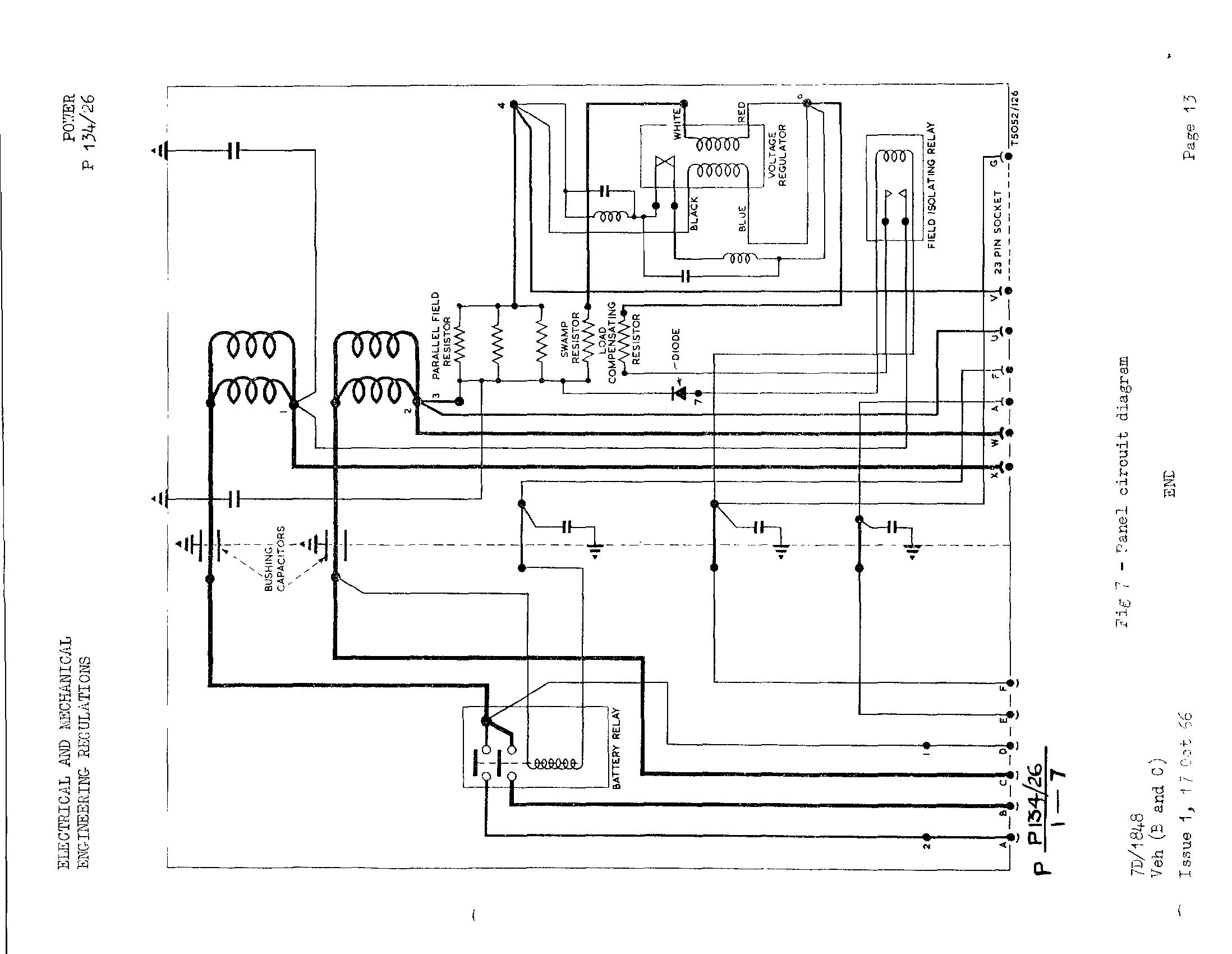
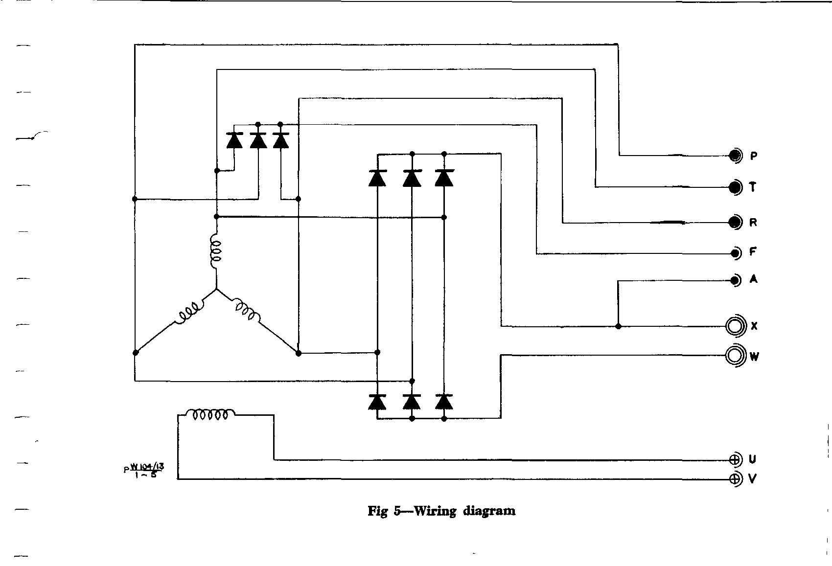
Clive Elliott was kind enough to send me some scanned copies of the generator circuit diagrams taken from EMER manuals. These are Panel Generator No. 9 Mk. 2 from EMER POWER W 134/26, and Generator No. 10 Mk. 2 from EMER Power W 104/13.
24v (FFR) Electrics
The electrics of a 24v Land Rover, are one of those things which divide the Land Rover community. Alas, many people think its just not worth the hassle, bits are expensive and hard to get. Maintenance is also meant to be impossible.
This isn't quite true. If it was, why did/does the British Army use FFR vehicles?
24v systems run better because of the better spark (true FFR systems even have platinum-tipped spark plugs). The cabling is also of lower resistance (or, read another way, thinner cabling can be used instead). True, the 2.4kW alternator could power a small town, but at least it will power those new halogen lights and a full suite of accessories - unlike the standard alternators.
Cost is given as a huge problem. It is true that new parts are expensive (GBP 1000-ish for a new alternator), but with so many people converting to 12v, secondhand alternators can be bought for GBP 20. I paid about GBP 100 for a full set of 24v electrics. You couldn't do that with 12v.
24v to 12v step-down regulators can be purchased from truck accessory suppliers for about GBP 20-30, so 12v radios,etc are not a problem either. Smaller 12v voltage regulators can be built if 12v gauges are required. I have done this for the two temperature gauges.
As for maintenance: When it comes down to it, there's little difference, although some items (eg. the HT electrics) are shielded. I have to admit I do run with a civilian unshielded distributor, so these cables are off-the-shelf unshielded cables. I'm still running at 24v though!
I recently managed to destroy the generator panel and shunt panel on my vehicle. It can be possible to find the problem and correct it, but it is often easier to replace with a "new" unit. During my electrical "rebuild", I did produce some diagrams. These might be of use to other people and are included here:
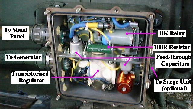
Generator Panel Innards: Late Version (transistorised)
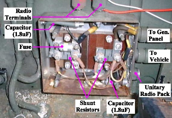
Shunt Panel Innards: Early Version (twin shunt)
Emission Controls
The civilian SIII Workshop Manual describes a number of emission gadgets fitted to the 2.25l petrol engine. Yes, you've guessed - they're different on the military versions! The two systems are very similar, but note that the military version includes a flame trap connecting the crankcase breather to the air intake hose. Note also, that the devices are connected differently. For example, the civilian crankcase breather is connected to the non-return-valve, instead of the air intake hose.
The layout described and pictured in the Army's User Handbook, matches the layout which I have. The military flame trap is Rover Part No. 603330. This is the same flame trap as is fitted to civilian 2.6l 6cyl engines. The User Handbook recommends that the trap is changed regularly.
Return MOD Series III User Manual Extract page.
Return to the main Land Rover page.
Do NOT deep-link directly to individual images on this page: it will NOT work!
Instead, you are welcome to link to this web page. This WILL work.

© Copyright 1996-2019, Richard Marsden